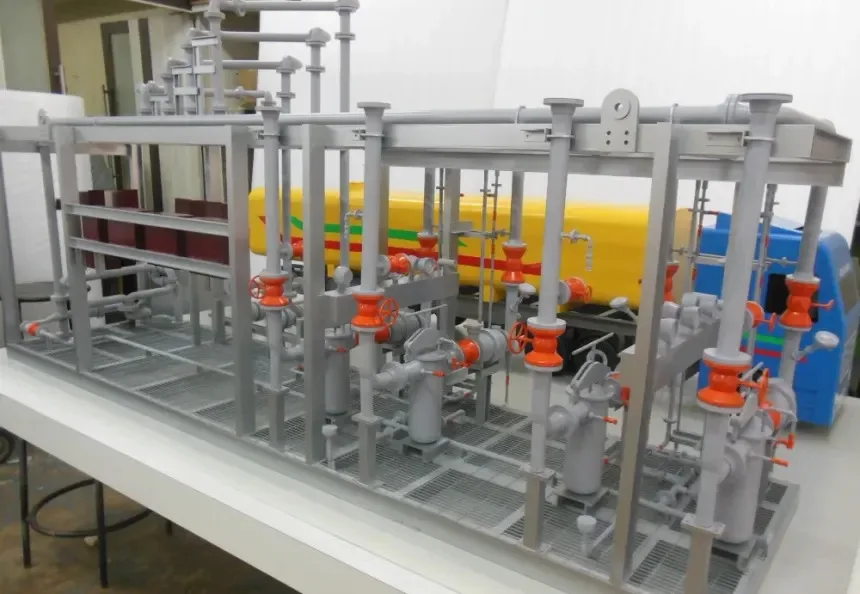
Plant design software has become remarkably sophisticated over the past decade, yet physical models have not disappeared from engineering offices and construction sites. If anything, a well-built piping model remains one of the most effective ways to communicate pipe routing, clash points, and spatial constraints to teams who are not spending their entire day inside CAD software.
What a Physical Model Adds to a Digital Design
3D plant design software is excellent for detailed engineering work, but reviewing a routing layout on a screen still requires navigating menus, rotating views, and interpreting scale in a way that does not come naturally to everyone in a project meeting. A physical model removes that barrier entirely — contractors, safety officers, and clients can look at a pipe rack from any angle simply by walking around the table.
Site teams in particular find physical references useful during construction, since a model sitting in the site office gives installation crews a quick visual check against the digital drawings without needing a laptop or a printed isometric for every section of the plant.
Where Piping Models Are Used Most
Process industries such as chemical manufacturing, refining, and pharmaceuticals commonly commission models during the detailed engineering phase, when pipe routing, valve placement, and equipment connections are being finalised. Power plants and water treatment facilities use similar models to coordinate between civil, mechanical, and instrumentation teams working on the same congested plot.
Training departments also rely on these builds, using a simplified physical layout to teach new operators and maintenance staff how a system is laid out before they encounter the full-scale, and often much more confusing, real installation.
How These Models Are Built
Base structures — pipe racks, support steel, and equipment foundations — are typically fabricated from acrylic or metal framing for durability, since these models often see heavy handling in site offices and training rooms. Pipe runs, valves, and fittings are usually 3D printed or built from standard model-making tubing, colour-coded to match the plant’s actual piping specification for different fluid services.
Scale is chosen based on how much of the plant needs to be represented — a single unit or pipe rack section might be built at a larger, more detailed scale, while a full plant overview is typically more compact and simplified to keep the build manageable.
Catching Design Issues Before Construction
One of the most valuable uses of a piping model is clash detection during design review meetings. Even with clash-detection software already run on the digital model, physically viewing a congested pipe rack often reveals accessibility and maintenance concerns that are easy to overlook on a screen — for instance, whether there is enough clearance to remove a valve for servicing once the rack is fully built out.
Catching these issues at model-review stage, rather than during actual construction, saves significant rework costs, which is a major reason engineering firms continue to justify the expense of a physical build alongside their digital design tools.
Choosing the Right Approach for Your Project
Not every project needs a full-plant model. For smaller reviews, a section model focused on a specific congested area often delivers most of the benefit at a fraction of the cost and lead time. Discuss your priorities with the model-making studio early — whether the goal is investor presentation, construction coordination, or operator training — since each use case calls for a different level of detail and durability.
It also helps to decide upfront whether the model needs to be modular. Plants that undergo frequent modifications benefit from a build where individual pipe rack sections can be swapped or updated without disturbing the rest of the model, saving significant cost over the life of the facility compared with a fixed, single-piece construction.
Working From Accurate Engineering Data
The quality of this kind of build depends heavily on the completeness of the data supplied to the studio. Isometric drawings, P&ID documentation, and equipment layout plans all need to be current and consistent with one another, since discrepancies between documents are often only discovered once fabrication has already started.
Studios experienced with process plant builds typically flag inconsistencies back to the client during the design review stage rather than making assumptions, which prevents a completed model from silently reflecting an outdated or incorrect design revision.
Durability for Site and Training Environments
A build destined for a site office or training room needs to withstand far more handling than one built purely for a boardroom presentation. Reinforced joints, sturdier base materials, and protective coatings on smaller components all extend the working life of a model that will be picked up, pointed at, and occasionally bumped on a regular basis over several years.
Discussing the intended environment with the studio before fabrication begins allows them to select materials suited to that level of wear, rather than defaulting to finishes intended for a one-time display piece.
A Long-Term Reference Tool
A well-planned piping model earns its keep across multiple stages of a project, from early design review through to years of use as a training and orientation tool once the plant is operational.
Supporting Contractor Coordination on Site
Construction sites for process plants typically involve several contractors working in close physical proximity — civil, structural, mechanical, and piping teams often need access to the same congested area within the same week. Having a shared physical model in the site office gives contractor supervisors a quick, unambiguous way to plan sequencing and avoid scheduling conflicts that drawings alone sometimes fail to make obvious.
Site engineers frequently report that a five-minute conversation around a physical model resolves coordination questions that might otherwise take several email exchanges and a follow-up meeting to sort out.
A Practical Complement to Digital Design Tools
None of this suggests physical models should replace digital plant design software — the two work best together. Digital tools handle the heavy engineering calculations, clash detection algorithms, and detailed documentation that a physical build simply cannot replicate, while the physical scale representation handles the communication and spatial understanding that digital tools, viewed on a screen, still struggle to convey as intuitively to a broad audience.